Your browser does not support JavaScript!
Skip to content Skip to navigation menu

Group safety standard ISO14119:2013 | India

ISO14119 is the standard (Type-B standard) that establishes “Safety of machinery—Interlocking devices (Note 1) associated with guards—Principles for design and selection” and primarily addresses the following topics:
・Types and classification of interlocking devices;
・Stopping the machine while the guard is open;
・Locking the guard while a hazardous machine function is operating according to the time necessary to stop the machine;
・Measures to minimize  defeat possibilities (Note 2) of interlocking devices attempted in a reasonably foreseeable manner; and 
・Requirements for the design and selection of guards and interlocking devices based on the matters listed above.
 

Note 1) An interlocking device or interlock is a mechanical, electrical, or other type of device that is designed to prevent the operation of a hazardous machine function under specified conditions (generally as long as the guard is not closed). Note that IDEC uses the word “interlock switch” to call an interlocking device or interlock that is designed to detect the opening and closing of doors.

 
Note 2)  Defeat is the action that makes interlocking devices inoperative or bypasses them. As a result, the machine is used in a manner not intended by the designer or without the necessary safety measures.

Note that given below are quotations from part of  ISO14119:2013 and IDEC’s explanation of them according to IDEC’s interpretation. If you have any questions or concerns, please refer to the original texts of ISO as well.


As shown in Figure 1 and Table 1, interlocking devices associated with guards are divided into the four types, i.e., Type 1 to Type 4, according to whether the  actuation principle is mechanical or non-contact, and whether the actuator is exclusively designed or not. Each type has different ease of  defeat and thus different requirements for the combination with a guard.


Click here for a description of the Type 2 interlock device (safety switch).


Click here for a description of the Type 4 interlock device (non-contact safety switch).

“Coded” shown in Table 1 represents whether the actuator is exclusively designed to actuate a particular interlocking device.
For example, in the case of a Type 3 magnetic interlocking device, every type of metal that reacts to magnetism can actuate the interlocking device in place of a regular actuator. In this case, the actuator of a Type 3 magnetic interlocking device is regarded as uncoded.
A Type 2 tongue-actuating position switch (IDEC calls this “an interlock switch”) has the actuator that is exclusively designed. This prevents the interlocking device from being actuated ( to minimize defeat possibilities) with tools that are easily available at a factory field, including a ruler and screwdriver. In this case, the actuator of a tongue-actuating position switch is regarded as coded.

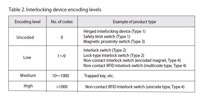
As shown in Table 2,  cording levels of actuators are divided into Uncoded, the Low, Medium, or High level according to the number of codes. The larger the number of codes is, the more difficult  defeat becomes.


Conditions that require an interlocked guard with guard locking

In general, in order to prevent people from being involved in an accident due to an operating hazardous machine function, the hazardous machine function is enclosed with a guard. Although enclosing it with a completely and entirely fixed guard is safe, it is not realistic in light of convenience for tasks such as putting in and taking out work, maintenance including cleaning, and set-up change. It is common practice, therefore, to design an interlocked guard in which part of the guard is used as a door (movable guard) and which is equipped with an interlocking device to detect the opening and closing of the door. An interlocked guard has the function of allowing a hazardous machine function to operate as long as the door is closed while halting it as long as the door is open, thus keeping a balance between productivity and safety.

For such an interlocked guard, the first consideration is whether or not it requires a lock (locking).
 In this case, a matter to be considered is the relationship between the following two kinds of time:
・ Access time, or time taken by a person to reach the hazardous machine function after opening the door; and
・ A time interval between the stop command given while the interlocked guard is open and the termination of the hazardous machine function (Note 3) (this is called the overall system stopping performance).

 
Note 3) The termination refers to a state in which hazardous factors are reduced to a level that does not cause injury or health impairment. Note that the termination can be achieved even before the machine comes to a complete stop, and if it is impossible to determine the time point that the termination was achieved, the time necessary for the machine to come to a complete stop should be considered.


As shown in Figure 2, the need for a lock in an interlocked guard is determined on the basis of the relationship between these two kinds of time.
・If the overall system stopping performance < access time, the interlocked guard does not require a lock, and therefore, an interlocked guard without guard locking will be used.
(This is because a hazardous machine function terminates before a person opens the door and approaches it.)

・If the overall system stopping performance ≥ access time, the interlocked guard does require a lock, and therefore, an interlocked guard with guard locking  shall be used.
(This is because a hazardous machine function does not terminate before a person opens the door and approaches it. For the lock to be released, the hazardous machine function needs to have terminated.)

As mentioned earlier, if the overall system stopping performance < access time, a hazardous machine function terminates before a person opens the door and approaches it, making it unnecessary for the interlocked guard to have a  lock for safety purposes. 
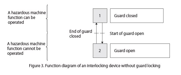
As shown in Figure 3, an interlocking device without guard locking allows a hazardous machine function to operate while the guard is closed. At the same time, the guard can be opened at any time, and while the guard is open, the device does not allow a hazardous machine function to operate.


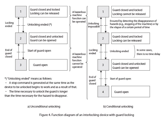
As mentioned earlier, if the overall system stopping performance ≥ access time, the interlocked guard needs to have a lock to prevent a person from approaching a hazardous machine function before it terminates. Note that an interlocked guard with guard locking has the two types of unlocking conditions as shown in Figure 4. One is “a) unconditional unlocking” and the other is “b) conditional unlocking.”


The above a) unconditional unlocking refers to a type of locking that an operator can release at any time. This type however is subject to conditions. For example, after an operator presses a release button to generate a stop signal, the time it takes to terminate a hazardous machine function needs to be shorter than the time it takes to release the locking.
The other b) conditional unlocking refers to a type of locking that an operator can unlock only after a hazardous machine function has terminated. To meet this condition, the termination of a hazardous machine function needs to be detected in some  means.

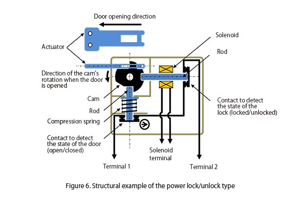
If the overall system stopping performance ≥ access time, and an interlocked guard with guard locking is required, the guard locking type needs to be one shown in either Figure 5 or Figure 6. 

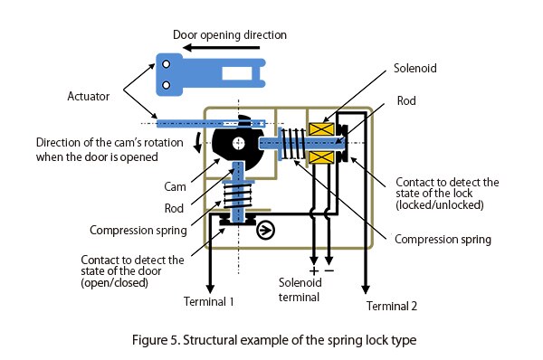
Spring lock type: Locked by spring force,  unlocked by power-on to the solenoid


Figure 5 shows the state in which no voltage is applied to the solenoid terminal. At this time, the force of the spring moves the rod to the left in the Figure to lock the cam.
When a voltage is applied to the solenoid, solenoid is exited to move the rod in the right direction in the Figure, releasing the cam lock.

Power lock/unlock type: Locked by power-on to the solenoid, unlocked by power-on to the solenoid


Figure 6 shows the state in which a voltage is applied to the solenoid terminal in a certain direction. At this time, the force generated by the excitation of the solenoid moves the rod to the left in the Figure to lock the cam. 
When a voltage is applied to the solenoid in the reverse direction, the force generated by the excitation of the solenoid reverses its direction, moving the rod in the right direction in the Figure and releasing the cam lock.

In Figure 6 “Power lock/unlock type:  Locked by power-on to the solenoid, unlocked by spring force ,”  a lock is not required for safety purposes; it can only be used to protect a production process (e.g., a case in which it is desirable to prohibit anyone to open the door without permission).

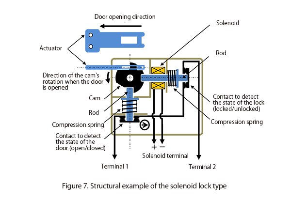
Solenoid lock type:  Locked by power-on to the solenoid, unlocked by spring force 


Figure 7  shows the state in which a voltage is applied to the solenoid terminal. At this time, the excited solenoid moves the rod to the left in the Figure to lock the cam. 
When applying a voltage to the solenoid is stopped, the force of the compression spring moves the rod in the right direction in the Figure to release the cam lock.

For more detailed explanations of “Locked by spring force, power-released” and “Power-locked, released by spring force,” please click on the link below:
Erroneous positioning of an interlocking device main body or an actuator as well as positional shifts due to vibration/impact during use could have negative effects such as inability to properly detect the opening and closing of doors, and damage to the interlocking device. To address this, the requirements for the installation of interlocking devices are  specified as below.

Requirements for the installation of interlocking device main bodies

In order to maintain the position of the device properly installed in accordance with manufacturer’s instructions, the following requirements need to be met:
・  To ensure reliable installation, and to require tools (Note 4) to loosen the device.
Note 4) Makeshifts, including a coin or a nail file, cannot be regarded as tools.
・  For the Type 1 interlocking devices, to have a method for fixing the position permanently after adjustment (e.g., pins, dowels).
・  To have access to the interlocking device for maintenance and operation checks. However, the prevention of  defeat attempted in a reasonably foreseeable manner must be considered.
・  To prevent the device from spontaneously loosening.
・  To prevent  defeat of the interlocking device attempted in a reasonably foreseeable manner.
・  To be located and, if necessary, protected so that damage from foreseeable external causes is avoided.
・  To follow manufacturer’s instructions regarding the positional relationship between the actuator and the interlocking device main body.
・  Not to use the device as a mechanical stopper ( Unless the manufacturer permits).
・  Not to create a gap of the guard where a part of human body could enter inside and cause an accident, by misalignment of the installation.
・  To install the device firmly so that its correct movements can be maintained.
・  For the Type 2 interlocking devices, to have a dust protection cover or alternative means at an opening through which the actuator is inserted, or by installing the device in an orientation that can prevent dust from entering through the opening, in order to avoid the contamination and deterioration of machine parts due to dust.

Requirements for the installation of actuators 

In order to minimize the possibility of a device loosening or shifting from its proper installation position during the expected life, the following requirements need to be met:
・  To ensure reliable installation, and to require tools (Note 4) to loosen  fasteners of the actuators.
Note 4)  An improvised implement such as a coin or a nail file cannot be considered as a tool.
・  To prevent the  actuator from spontaneously loosening.
・  To be located and, if necessary, protected so that damage from foreseeable external causes is avoided.
・  Not to use the  actuator as a mechanical stopper ( Unless the manufacturer permits).
・  To install the  actuator firmly so that its correct movements can be maintained.


If the overall system stopping performance ≥ access time, and an interlocked guard with guard locking is required, specified conditions need to be satisfied to start a hazardous machine function. That is, both the conditions that the door is closed and locked need to be satisfied.
For example, as shown in Figure 5,  the contact to detect the state of the door (open/closed) and the contact to detect the state of the lock (locked/unlocked) connected in series can satisfy these conditions.
Alternatively, realizing the NC contact, which works only while the door is closed and locked, in the structure of an interlock switch will also be able to satisfy these conditions.
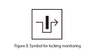
This type of circuit, which can start a hazardous machine function only while the door is closed and locked, has the locking monitoring mark shown in Figure 8.


As stipulated in ISO12100, when safety measures were taken as a result of risk assessments, it is important to confirm that they will not create a new hazard. This also applies in cases where an interlocked guard with guard locking is required for safety purposes. When the overall system stopping performance ≥ access time, and an interlocked guard with guard locking is installed to prevent people from approaching it until a hazardous machine function terminates, it is necessary to confirm that the installation has not created a new hazard. There are a variety of machines, large and small, and those requiring particular attention are large ones that have an interlocked guard with guard locking that is large enough to accommodate a whole human body. For these large machines, it is necessary to confirm that locking the interlocked guard with guard locking will not create a new hazard by trapping a worker or maintenance worker in the machine.

If such a new hazard can be created, the machine needs to be equipped with the “emergency release function” to release the guard locking from outside in case of an emergency and the “escape release function (Figure 9)” to release the guard locking from inside. In addition, to address a situation in which an interlocked guard with guard locking fails and needs to be released from outside, the “auxiliary release function (Figure 10)” may be required.
 

IDEC offers various interlock switches with these unlocking functions. Please select products that meet your needs.


Locking strength against a static force and Locking strength against a dynamic force

When an interlocked guard requires guard locking, the locking strength of the interlocking device needs to be checked. This is because if the force that exceeds the locking strength specification value causes damage to the locking mechanism, a person will be exposed to an operating hazardous machine function.

To avoid such a situation, it is necessary to select a lock type interlock switch with specifications that meet the required locking strength by taking into account matters such as the weight of the door and the power used to move the door (moved by human power, or motor, etc.).

It should be noted that the specifications of interlock switches generally state the locking strength against a static force. The locking strength specification value represents a value that indicates the maximum force it can withstand when a force is slowly applied in the door opening direction in the locked condition.

For example, when a door is forcefully closed, the bouncing back or the machine vibration can apply dynamic forces to the locking mechanism, but these dynamic forces are not considered in locking strength specification values. Therefore, if the bouncing back or the machine vibration occurs repeatedly in the actual operation of the machine as a result of forcefully closing the door, those dynamic forces could lead to unexpected malfunctions or damage to the locking mechanism, even if the dynamic forces are below the locking strength specification value.

To address this, a machine design is required that minimizes the bouncing back or the machine vibration that occurs when the door is forcefully closed. It is also important in terms of safety to examine how the locking mechanism is damaged in case it is damaged. It is recommended to examine, before designing the machine, whether the machine stops (a safe failure), or does not stop (a dangerous failure), or both can happen according to time and circumstances.

IDEC offers various locking type interlock switches that take into consideration failure modes  in case of the damage of a locking mechanism. Please select products that are suited for your applications.

Interlocking devices may be  defeated for a variety of reasons. For example, people may want to  defeat an interlocking device in order to operate the machine for adjustment work while leaving the door open, in order to work while leaving the door open to avoid the troublesome task of opening and closing the door frequently, and in order to improve work efficiency as troubles/failures of an interlocking device cause the machine to stop frequently. However,  defeating an interlocking device can compromise the safety of the worker and lead to a significantly higher possibility of unexpected accidents.
This is why preventing  defeat of interlocking devices is important.

One is to improve the design and working processes of the machine, for example by making it easier to operate, so that the incentive to defeat is fundamentally less likely to arise.
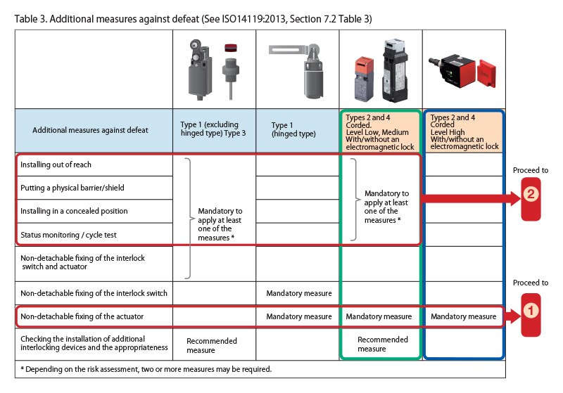
Secondly, if it is difficult to eliminate the incentive to defeat, then the measures specified for each type of interlock device, as shown in Table 3, will prevent defeating in a reasonably foreseeable manner.
Note)  Defeat of interlocking devices that is attempted manually or using  readily available objects. It includes removing an interlocking device main body or an actuator using tools necessary for the intended use of the machine, or  readily available tools (i.e., a screwdriver, wrench, hexagonal wrench, pliers). The  readily available objects include things that are used in our daily lives, such as a screw, needle, a piece of metal, key, coin, adhesive tape, string, and wire, as well as a spare actuator.

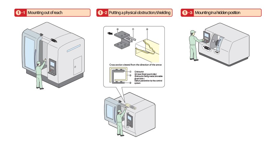
Note) Additional measures against defeat taken in terms of the installation position or installation method of an interlocking device (①-1 to ①-3) need to be examined for their effectiveness with the machine installed at the field.
 

Prevention of accessibility to the elements of the interlocking device

Defeat prevention by the control system

Non-detachable fixing


 Interlocking devices are safety-related parts of the control system(SRP/CS) of a machine, or a subsystem or a subsystem element of a safety-related
electrical control system (SRECS). They may have the required performance levels (PLr) or necessary categories that are  specified in a machine-specific individual safety standard in order to prevent the actuation of hazardous machine functions while the door is open. Please confirm the relevant machine-specific individual safety standard.
For further information  on the required performance levels and categories, please click on the link below: